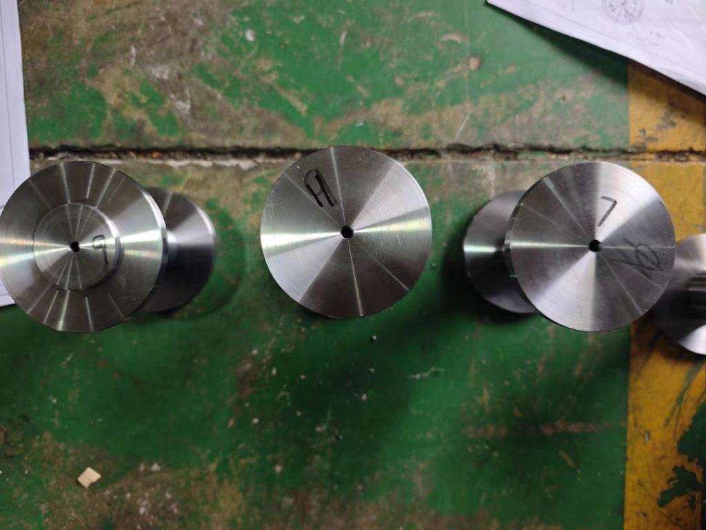
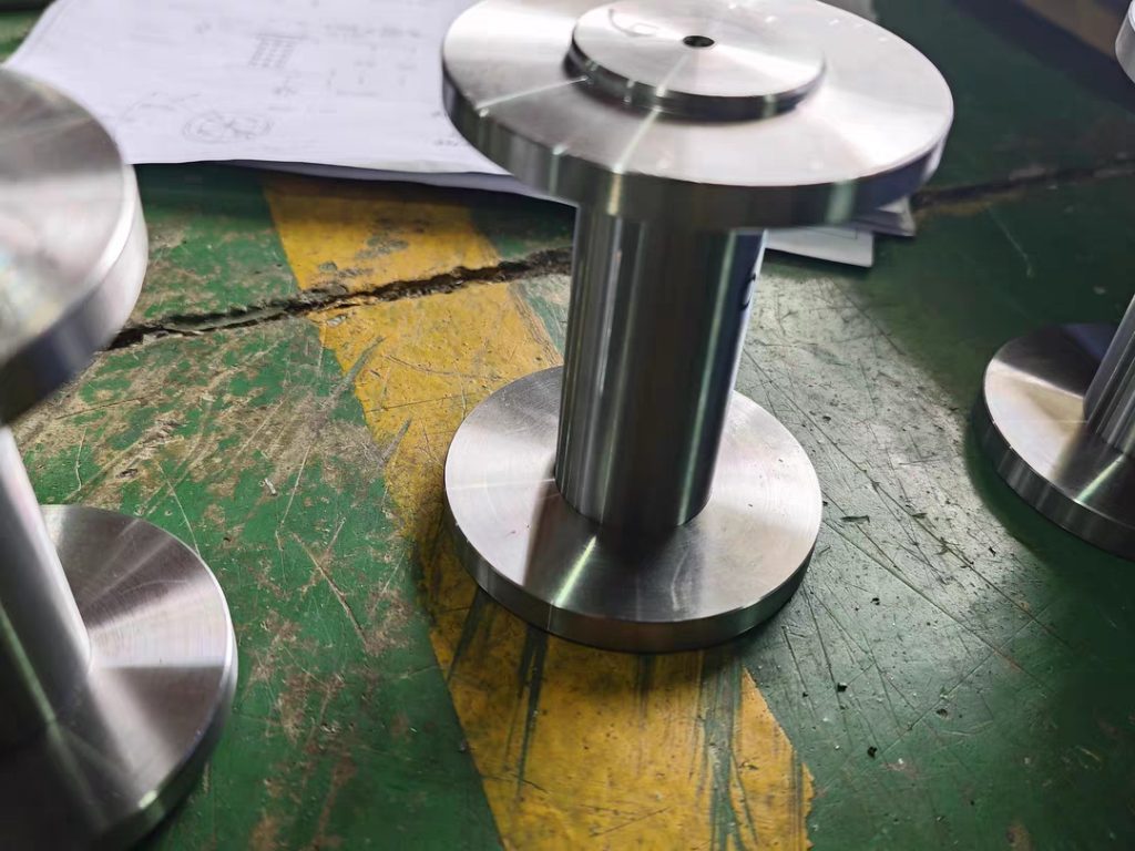
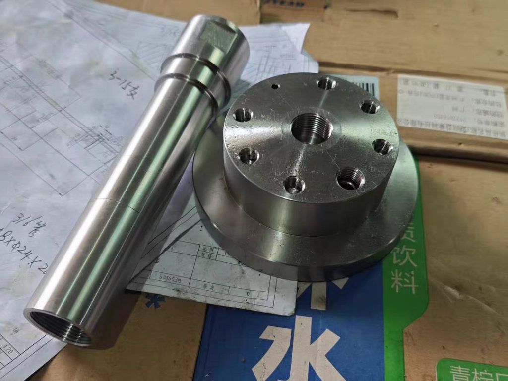
You open the box. The parts look perfect. You measure a few random dimensions with calipers — all good. But when you start assembling, something is wrong. The bearing is too tight. The housing won’t close evenly. Two mounting holes don’t line up.
Sound familiar?
In my 12 years running a CNC shop floor, I’ve seen this nightmare happen too many times. And here’s the truth: it’s almost never because the machinist couldn’t cut metal. It’s because the tolerance logic was broken before the first chip was made.
If you want parts that fit, stop thinking about “tight tolerances” and start thinking about correct tolerances. Here is the exact internal checklist we use at our factory to prevent tolerance disasters for our clients.
1. The “Hidden Default” Trap on Drawings
Most tolerance issues are born in the title block. Engineers often leave dimensions untoleranced and forget to specify a general standard. This forces us, the manufacturer, to guess. One shop might assume ±0.1mm; another might assume ±0.5mm. Both are “within spec,” but neither fits your assembly.
Our Solution: We strictly enforce ISO 2768-mK for general dimensions unless you tell us otherwise. For critical features, we demand explicit callouts. If your drawing says “Tolerance: ±0.05mm” everywhere, you’re paying for precision you don’t need on 90% of the part, and you’re increasing the risk of delays.
2. Datum Confusion: The #1 Cause of Assembly Failure
We recently had a client whose bracket wouldn’t fit. His drawing used the bottom edge as the primary datum. But in his assembly, the part was located by two pins on the top surface. This created a massive tolerance stack-up.
Our Solution: We always ask: Where does this part sit in the real world? We match our machining datums and inspection datums (CMM alignment) to your assembly datums. If your drawing doesn’t define a logical datum structure, our engineering team will flag it and suggest a fix before production starts.
3. Managing the “Silent Killers”: Heat and Stress
Material moves. Aluminum expands when it gets warm from cutting. Stainless steel work-hardens and springs back. If a part is roughed too aggressively, it will warp the moment you unclamp it.
Our Solution: For high-precision parts, we use stress-relieving techniques between operations. We control coolant flow to minimize thermal growth. And for thin-walled components, we design custom soft jaws to distribute clamping force evenly, preventing deflection.
4. Why “±0.01mm Everywhere” is a Red Flag
If you ask for ±0.01mm on every dimension, including non-functional cosmetic edges, two things happen:
-
The price triples.
-
The lead time doubles.
-
The part still might not fit (because of stack-up).
Our Solution: We apply the “80/20 Rule” to tolerances. We use tight tolerances (like ±0.01mm or better) only on mating surfaces, bearing seats, and threaded holes. Everything else stays at standard commercial tolerance. This keeps your cost down and ensures the critical features are stable.
Conclusion: Don’t Just Buy Parts, Buy Expertise
Avoiding tolerance issues isn’t about finding a machine that can count to 0.001. It’s about finding a partner who understands physics, materials, and assembly.
At [Your Company Name], we don’t just run programs. We review your drawings, identify potential tolerance traps, and provide a free DFM (Design for Manufacturability) analysis with every quote.
Ready to stop fighting tolerance issues?
Upload your STEP file or DWG drawing today, and let our engineers show you how to make it right the first time.


No reply content