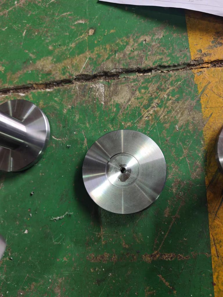
When ordering custom CNC machining parts, one of the first questions a manufacturer may ask is simple: Can you send the drawings and CAD files?
For buyers, preparing the right technical files can make the quotation and production process much easier. A manufacturer needs enough information to understand the geometry, dimensions, material, tolerances, surface requirements, and quantity before confirming how a part should be produced.
Sending only a product photo or a basic 3D model may not always provide enough manufacturing information.
This guide explains which drawings and files buyers should prepare when requesting custom CNC machining parts, what each file is used for, and which technical information should be included before production.
1. Why CNC Manufacturers Need Technical Drawings
A CNC machining manufacturer cannot manufacture a precision component reliably based only on a general description such as:
“I need 500 aluminum parts.”
The manufacturer needs to understand exactly what the finished component should look like and which dimensions are important.
A technical drawing can define:
- Overall dimensions
- Hole sizes
- Hole positions
- Threads
- Angles
- Radii
- Tolerances
- Surface roughness
- Material
- Surface treatment
- Special inspection requirements
The more important a dimension is to the function of the part, the more clearly it should be specified.
A detailed drawing also gives different manufacturers the same technical information when you are comparing quotations.
2. 3D CAD Files for CNC Machining
A 3D CAD model is one of the most useful files for a CNC machining project.
Common 3D formats include:
- STEP
- STP
- IGES
- IGS
- Parasolid
- Other CAD formats supported by the manufacturer
STEP files are widely used because they can transfer the three-dimensional geometry of a component between different CAD systems.
A 3D model helps the manufacturer understand:
- Part geometry
- Curved surfaces
- Pockets
- Holes
- Slots
- Chamfers
- Fillets
- Overall shape
For complex components, a 3D model can be particularly useful during engineering review and manufacturing preparation.
However, a 3D model does not necessarily replace a complete technical drawing.
3. Why You May Also Need a 2D Technical Drawing
A 2D drawing can provide information that may not be obvious from a 3D model.
For example, the CAD model may show the geometry of a hole, but the technical drawing can specify:
- Hole tolerance
- Thread specification
- Positional tolerance
- Surface roughness
- Required finish
- Critical dimensions
- Inspection requirements
A 2D drawing can therefore act as the manufacturing reference for the finished part.
For precision CNC components, providing both a 3D CAD model and a detailed 2D drawing is often a practical approach.
4. What Should Be Included on a CNC Drawing?
Before sending a drawing to a manufacturer, check whether it contains the information needed for production.
Part Dimensions
Include important dimensions such as:
- Length
- Width
- Height
- Diameter
- Hole depth
- Pocket depth
- Wall thickness
- Radius
- Chamfer dimensions
Tolerances
Not every dimension necessarily needs an extremely tight tolerance.
Identify critical dimensions clearly and specify the required tolerance.
For example:
- ±0.10 mm
- ±0.05 mm
- ±0.02 mm
The appropriate tolerance depends on the function of the component.
If you need help understanding CNC tolerances, you can also review What CNC Machining Tolerances Can Chinese Manufacturers Achieve?
Avoid specifying unnecessarily tight tolerances for every dimension because tighter tolerances can increase manufacturing and inspection requirements.
5. Specify the Material Clearly
Do not simply write:
Aluminum
when your application requires a specific material grade.
Depending on the project, you may need to specify:
- Aluminum grade
- Stainless steel grade
- Carbon steel grade
- Brass grade
- Copper grade
- Engineering plastic
- Other specialized materials
The material can affect machining performance, mechanical properties, surface treatment, weight, corrosion resistance, and cost.
If you are unsure about the available options, see What Materials Can Chinese CNC Parts Manufacturers Machine?
6. Surface Finish Requirements
The drawing should identify any important surface finish requirements.
Depending on the application, you may need:
- Specific surface roughness
- Machined finish
- Polishing
- Brushing
- Sandblasting
- Anodizing
- Plating
- Powder coating
- Black oxide
- Passivation
For example, a component used inside a machine may have different surface requirements from a visible consumer product.
If appearance is important, describe the required finish rather than assuming the manufacturer will automatically know what you expect.
7. Threads and Holes Need Clear Specifications
Holes are among the most common features on CNC machined parts, but simply showing a hole on a drawing may not be enough.
Specify information such as:
- Hole diameter
- Hole depth
- Through hole or blind hole
- Thread type
- Thread size
- Thread depth
- Countersink
- Counterbore
- Hole tolerance
- Hole position
For threaded components, clearly identify the applicable thread standard and size.
This helps prevent problems when the finished part needs to connect with another component.
8. Identify Critical Dimensions
Not every dimension on a CNC part has the same importance.
If a particular dimension controls assembly or performance, identify it clearly.
Critical features might include:
- Bearing seats
- Shaft diameters
- Mounting holes
- Sealing surfaces
- Alignment surfaces
- Threaded holes
- Mating surfaces
When the manufacturer understands which dimensions are critical, inspection can focus on the features that matter most to the final application.
9. Provide the Correct Drawing Revision
One common problem in custom manufacturing is using an outdated drawing.
Engineering designs can change during development.
For example:
Revision A → Revision B → Revision C
If the buyer sends several versions of the same drawing, the manufacturer may not know which version is approved for production.
A simple revision system can help.
Include information such as:
- Part number
- Drawing revision
- Revision date
- Change description
- Approved version
Before production begins, confirm which drawing revision is the final manufacturing version.
10. Add the Part Number to Your Files
If you are ordering several components, give each part a clear part number.
For example:
- CP-001
- CP-002
- CP-003
- CP-004
The part number should appear consistently on:
- CAD file
- 2D drawing
- Purchase order
- Quotation
- Inspection report
- Packaging label
This makes communication easier when multiple components are being manufactured at the same time.
11. Tell the Manufacturer the Required Quantity
Quantity is an important part of a CNC quotation.
The same part may have very different economics at:
- 1 piece
- 5 pieces
- 20 pieces
- 100 pieces
- 500 pieces
- 5,000 pieces
When requesting a quotation, clearly state the expected quantity.
If you are still testing the design, you can ask for separate pricing for prototype and production quantities.
For example:
Prototype: 5 pcs
Production: 500 pcs
This gives the manufacturer a better understanding of your project.
12. Include the Application When Appropriate
You do not always need to disclose confidential product information, but explaining the general application can be useful.
For example:
This component is used in an industrial automation assembly.
or:
This aluminum housing is used for electronic equipment.
The application can help the manufacturer understand why certain requirements may be important.
For example, a component exposed to moisture may require different material or surface treatment considerations from an indoor mechanical component.
13. When a PDF Drawing Is Especially Useful
PDF technical drawings are convenient for reviewing manufacturing requirements because they can preserve the visual layout of the drawing.
A PDF can contain:
- Dimensions
- Tolerances
- Notes
- Material
- Surface finish
- Revision information
- Inspection requirements
When sending a quotation request, a combination such as:
STEP + PDF drawing
can provide both the 3D geometry and the technical manufacturing requirements.
14. Product Photos Can Be Helpful, But They Are Not a Substitute
Photos can provide useful visual context.
For example, a photograph can show:
- Existing production parts
- Assembly position
- Surface appearance
- Packaging
- Reference dimensions
However, photos usually cannot provide the precision information required for CNC production.
A photo should therefore be treated as supporting information rather than the primary manufacturing document.
15. What If You Do Not Have a Complete Drawing?
Not every buyer has an engineering department capable of preparing a complete CNC drawing.
If you only have:
- A physical sample
- A rough sketch
- A 3D model
- A product photograph
- An old drawing
tell the manufacturer what information you currently have.
The manufacturer may be able to determine what additional information is needed before providing a final quotation.
For reverse-engineering projects, additional measurement and engineering work may also be required.
Do not assume that a supplier can manufacture a precision part accurately from incomplete information without first reviewing the project.
16. How to Prepare an RFQ Package for CNC Machining
A simple RFQ package could contain:
1. 3D CAD file
For example:
CP-001.step
2. 2D technical drawing
For example:
CP-001-Rev-B.pdf
3. Quantity
For example:
500 pcs
4. Material
For example:
Aluminum 6061-T6
5. Surface treatment
For example:
Black anodizing
6. Special requirements
For example:
Critical dimensions marked on drawing
7. Destination
For example:
United States
This gives the manufacturer a much clearer basis for quotation.
17. Keep Your Files Organized
If you regularly purchase CNC components, create a consistent file structure.
For example:
Project Name
→ CAD
→ Drawings
→ Quotations
→ Inspection
→ Purchase Orders
→ Samples
→ Production Records
Use consistent filenames.
For example:
CP-001_Rev-A.step
CP-001_Rev-A.pdf
CP-001_Inspection-Report.pdf
This becomes especially useful when you place repeat orders several months later.
18. What CNC Manufacturers May Ask You to Confirm
After reviewing your files, a manufacturer may ask questions about:
- Material grade
- Tolerances
- Surface finish
- Quantity
- Thread specifications
- Critical dimensions
- Packaging
- Inspection
- Production schedule
These questions are not necessarily a problem. They can indicate that the manufacturer is reviewing the technical requirements rather than simply giving a generic price.
The faster you can answer these questions, the faster the quotation and engineering process can usually move forward.
19. Common File Preparation Mistakes
Sending Only a Product Photograph
A photograph does not normally contain enough information for precision machining.
Sending an Unfinished CAD Model
If the model does not represent the final design, clearly identify it as a preliminary version.
Forgetting Material Specifications
A manufacturer cannot accurately quote many CNC parts without knowing the required material.
Leaving Critical Tolerances Unspecified
Important assembly dimensions should be clearly identified.
Sending Multiple Drawing Versions Without Revision Numbers
This can create confusion about which design should be manufactured.
Forgetting Surface Treatment
Surface treatment can affect both production requirements and final cost.
Not Specifying Quantity
A quotation for one prototype and a quotation for 1,000 production parts may have very different cost structures.
20. A Simple CNC Drawing Checklist
Before sending your RFQ, check:
- [ ] 3D CAD model included
- [ ] 2D drawing included
- [ ] Correct file format
- [ ] Material specified
- [ ] Quantity specified
- [ ] Critical dimensions identified
- [ ] Tolerances specified
- [ ] Threads identified
- [ ] Surface finish specified
- [ ] Surface treatment specified
- [ ] Part number included
- [ ] Drawing revision included
- [ ] Special inspection requirements included
- [ ] Packaging requirements included if necessary
If these items are complete, the manufacturer has a much stronger technical basis for reviewing your project.
Frequently Asked Questions
What CAD file is best for CNC machining?
STEP files are commonly useful because they provide 3D geometry in a format that can be transferred between different CAD systems. However, the preferred format can depend on the manufacturer’s engineering software.
Do I need both a 3D model and a 2D drawing?
For many precision CNC projects, providing both is useful. The 3D model describes the geometry, while the 2D drawing can specify tolerances, surface requirements, threads, notes, and other manufacturing details.
Can a CNC manufacturer work from a STEP file only?
Sometimes, but it depends on the complexity of the part and the information contained in the file. If critical tolerances, surface finishes, or other requirements are not defined, a manufacturer may need additional information.
What information should be on a CNC drawing?
Important information can include dimensions, tolerances, material, surface finish, threads, special notes, inspection requirements, part number, and drawing revision.
Should I include the quantity when requesting a quotation?
Yes. Quantity can significantly affect CNC machining pricing because setup, programming, tooling, and production costs can be distributed differently across different order quantities.
Can I send a photo instead of a CAD drawing?
A photo can provide useful reference information, but it generally cannot replace a proper CAD model or technical drawing for precision CNC manufacturing.
What should I do if my drawing is incomplete?
Send the information you have and explain what is missing. The manufacturer can then identify which technical details need to be confirmed before production.
How do I prevent a manufacturer from using an old drawing?
Use clear part numbers and revision numbers, and explicitly identify the approved production revision before manufacturing begins.
Final Thoughts
The quality of the technical information you provide can have a direct effect on how efficiently a CNC machining project moves from quotation to production.
A complete 3D CAD model, detailed 2D drawing, clear material specification, defined tolerances, surface requirements, quantity, and revision information give the manufacturer a much clearer understanding of what you need.
For buyers sourcing custom CNC machining parts from China, preparing the technical package before requesting quotations can also make supplier comparisons easier because every manufacturer can quote against the same requirements.
If you are looking for a supplier for custom CNC machining parts, you can review the Custom CNC Machining Parts Manufacturer in Dongguan China profile on Vlefooena and discuss your CAD files, drawings, quantities, materials, tolerances, and production requirements directly.


No reply content